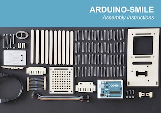
Arduino assembly instructions for our Arduino-Smile assembly kit. The kit includes all the components you need to assemble a 8×8 LED display, hook it up to an Arduino ONE, and run your first sketch showing a beating heart. Also includes a illustrated step-by-step instructions, as shown below. Enjoy. Just Make IoT!
Below you find illustrated step-by-step instructions on how to assemble a 8×8 LED display, hook it up to an Arduino ONE, and run your first sketch showing a beating heart. Enjoy
Can I buy one? Yes you can. Contact me for more information.
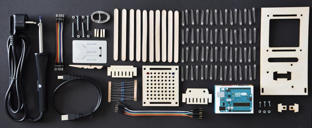
In the box
Overview of all the items you find in the Arduino-Smile box
The following items you find in the Ardiuno-Smile box
Download the illustrated instructions to build a 8×8 LED in PDF
It describes, step by step, how to assemble the 8×8 LED display, similar as below, but formatted in a way that you can print it out, or comfortable read it from a tablet.
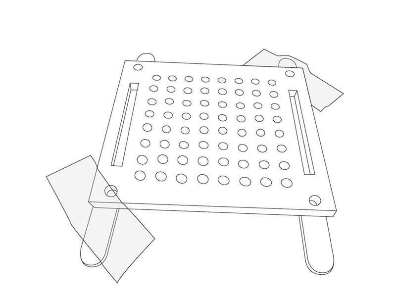
Prepare the LED panel. Open bag marked 1. Prepare the LED panel. Use two popsicle sticks to support the panel and apply a bit of scotch tape to tape it to the table.
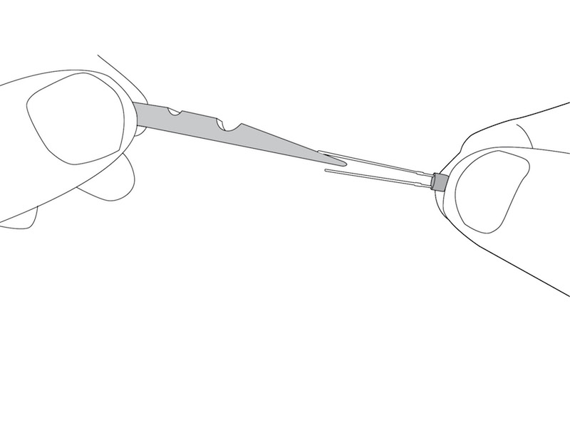
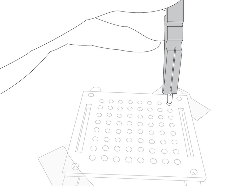
The LED tool. Use the clothespin to place the LED in the holes. Note that the LED has a long and a short pin.
The first LED LED. Start with the most distant row. Enter the LED, one by one, in the holes starting with the hole marked red. Make sure that the long pin is to the front.
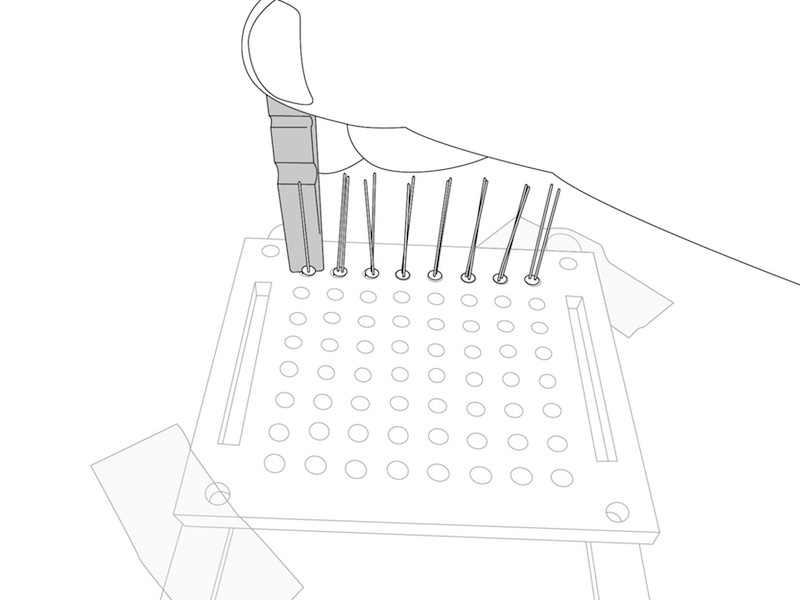
The first row. Complete the entire row. Again, check to make sure that all LED have the longest pin in front, i.e. towards you.
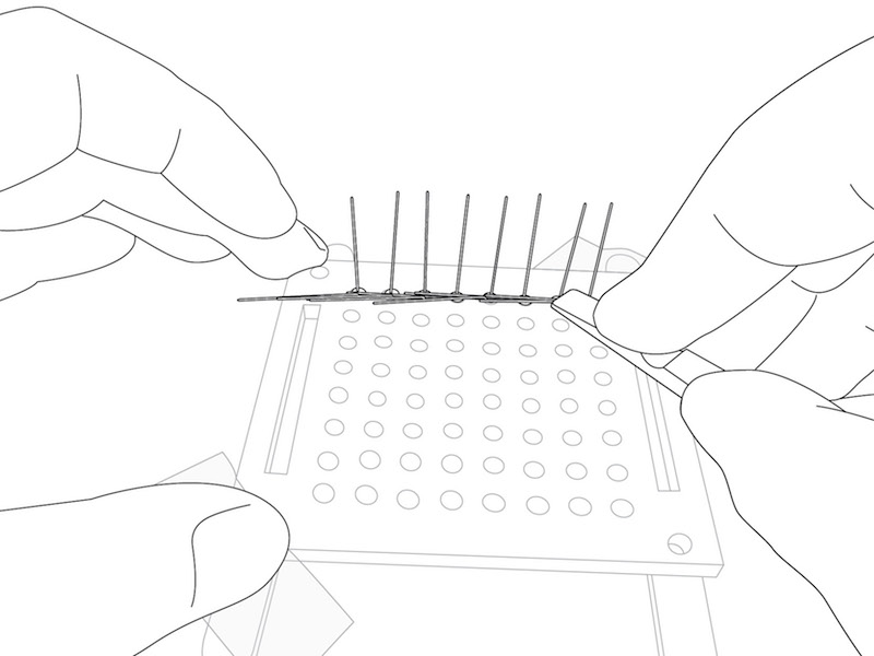
The first row – II. Fold the longest pin down using the clothespin. Make sure that the folded pins overlap so they can be soldered together. Also make sure that the folded pins do not touch the pin still standing.
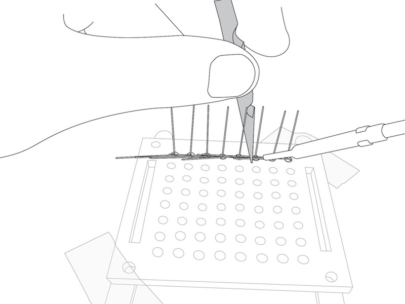
Soldering the LED-Pins. Carefully solder the pins toghether. Use caution and avoid touching the solder iron, it is hot! You can use the clothespin to hold the pin down while you are soldering.
Testing using the Arduino board. Preparing to TEST Ok. we want to check if everything is ok right from the start. What we do not want is to find out something is wrong after you have completed assembly becuase by then you will have no room anymore to fix anything. The items needed for this you find in bag number 2.
Connecting to Arduino We can use the Arduino for testing. Take a black wire from the bundle, and solder a resistor to the end. Also take a white wire. Connect the black wire and resistor to the 3v3 output. Connect the white wire to the GND output. Now you are ready to test.
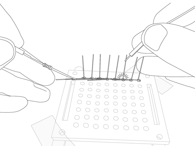
Testing. Hold the black wire and resistor against the long pins you just soldered together. One by one, hold the white wire to the still standing pin. Everything is good if the LED lights up.
Completing the rows. Take your time and now do the same for the remaining seven rows until all LED are placed and all long pins have been folded and soldered in horizontal lines.
Cutting the end-points. When you finished, cut the soldered LED-wires so that you can position the side-wall. After cutting the soldered wires, make sure to re-check eah of the LED. Cutting may break some of the connections.
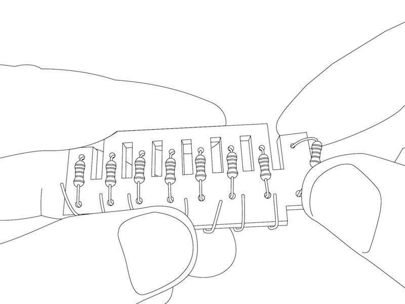
Preparing the resistor wall. Mount the resistors in the ‘Resistor-wall’. Make sure to place the resistor part in between the openings. This is needed so we can mount the connector through the bottom hole. Note; you need the resistor from the test-wire as well.
You can bend the bottom part around the wall to stabalize the resistors.
Placing the resistor wall. Place the ‘Resistor-wall’ in the LED panel. Bend the resistor wires such that each lines up with one of the soldered LED-wires.
Solder the resistors. Solder the resistor wires to the soldered LED-wires. After soldering test if everything is working by holding the black wire (3v3, now without resistor) against one of the resistors and holding the white wire (GND) against the LED pins still standing.
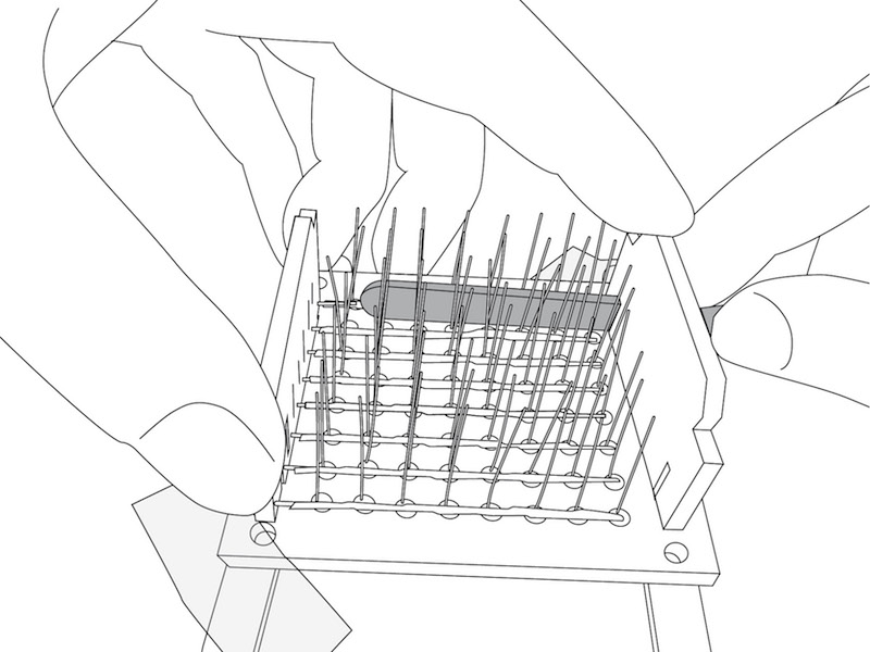
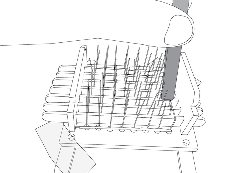
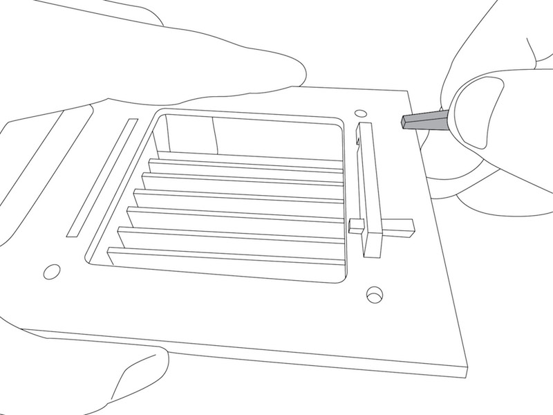
Place the ‘Feet-wall’. Mount the ‘feet-wall’ and slide in 8 popsicle sticks between the rows of wire.
Create the vertical lines. Bend the LED pins over the popsicle sticks, starting with the one in the lower right corner, marked blue. The last pin is bent back over the last popsicle stick, towards you.
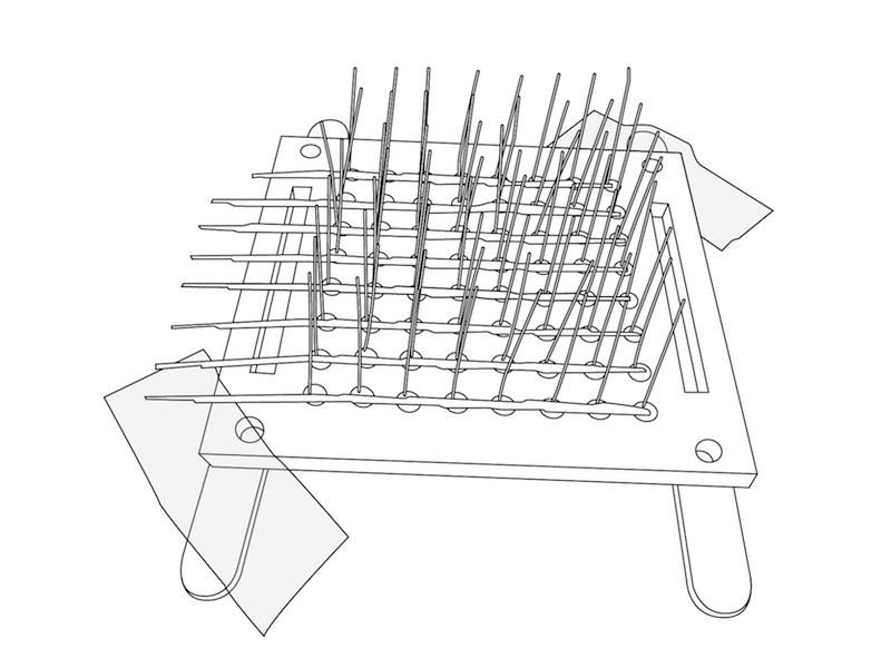
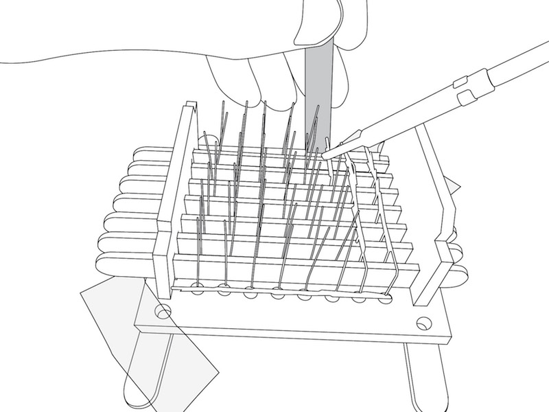
Solder the vertical lines. Then, solder the bent LED pins together. This gives an 8×8 grid, with horizontal lines connected with the resistors, and veritical lines on top of the lollipop-sticks.
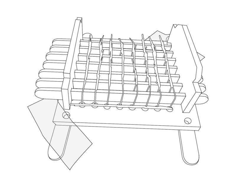
Grid finished! When finished you end up with an 8×8 grid. Horizontal lines, connected with the resistors, and veritical lines on top of the lollipop-sticks. In the same fashion as you have done before, you can test the grid by holding the black-wire (3v3) against the resistor and the white wire (GND) against a vertical line.
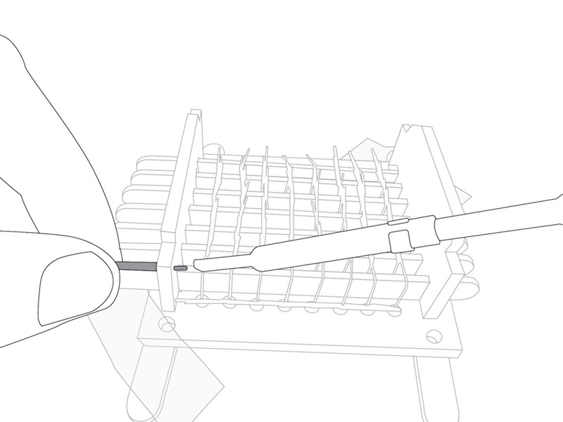
Connect the horizontal lines. In bag 3 you find the connection wires. One by one, place a short connection wire inside top hole next to the resistor, and solder the resistor wire to the connection wire. Remove the surplus wire.
Connect the vertical lines. Then solder a long connection wire at the end of each of the vertical lines. Hint: keep the same order of colors as used when connecting the resistor wires.
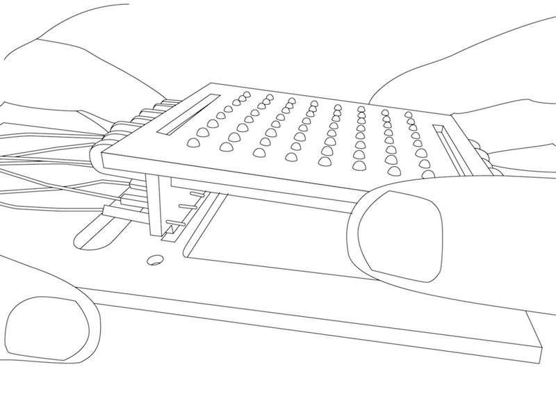
Place the LED Panel. Pull the connection wires coming from the vertical lines through the main opening in the motherboard. and place the LED panel.
Mount the LED panel. Then pull the connection wires up through opening marked with F on the ‘In the box’ page. Turn the motherboard around, and mount the ‘Feet-wall’ using two pegs.
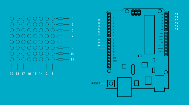
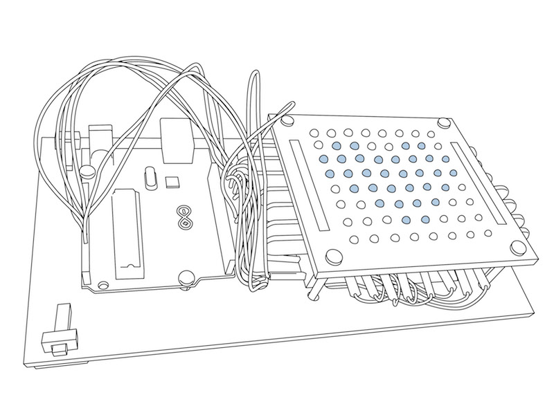
Connect the wires. Now connect the wires from the LED panel to the Arduino following the numbers as indicated in the scheme.
Congratulations! You have completed the preparation of the 8X8 display and you are ready to assemble your Arduino-Smile computer. The next section will show you how to: 1) Complete installation and the use of the Arduino IDE interface 2) Running your first programs 3 to ∞) Editing and creating your own programs
“Before uploading your sketch, you need to select the correct items from theTools > Board and Tools > Port menus. On the Mac, the serial port is probablysomething like /dev/tty.usbmodem241 (for an Uno). On Windows, it’s probably COM1 or COM2 (for a serial board) or COM4, COM5, COM7, or higher (for
a USB board) – to find out, you look for USB serial device in the ports section of the Windows Device Manager. On Linux, it should be /dev/ttyACMx , /dev/ ttyUSBx or similar. Once you’ve selected the correct serial port and board, press the upload button in the toolbar or select the Upload item from the Sketch menu. Current Arduino boards will reset automatically and begin the upload. The Arduino Software (IDE) will display a message when the upload is complete, orshow an error.”
Experience so-far. I’ve handed our a few sets and even had the opportunity to host a workshop at a middle school. Enthusiasm all around, but I’ve underestimated the skills and training needed to soldering. The purpose of soldering is to mount the item, not to deposit as much solder material as possible. Good learnings 🙂
Anybody interested in trying one, please contact me. I still have material for one or two sets.